
You bought the boat, you picked the spot, and you drilled the first hole. Then you realized the transducer cable is too short, the power wire is too thin, and the display bracket blocks your cup holder. Most Lowrance installs fail for the same three reasons: bad transducer placement, wrong wire gauge, and careless hole sealing. This guide walks you through each step so you don’t learn those lessons the hard way.
We’re covering the full process: choosing a mount style, dry-fitting the parts, wiring with a proper fuse, sealing every hole, and doing a water test before you commit to the final screw. You’ll also learn how to set the transducer type in the unit software and update firmware. By the end, you’ll have a setup that reads bottom at idle and holds a clean sonar picture at planing speed.
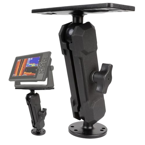
Leenconghui
Leenconghui Aluminum Alloy Fish Finder Mount with C Size 1.5" / 38mm Ball
- NOT compatible with: the Humminbird Helix 5, 7, 8, 9, 10, 12, 15, the Solix 10. The marine electronic mount consists of a 2.4" dia…
- The c size 1.5" rubber ball ensures a secure grip, capable of supporting up to 15.5 lbs at rest and 4.5 lbs in motion, while allow…
- Compatible with a wide range of fish finders, GPS chartplotters, and other marine electronics from brands such as Garmin, Humminbi…
Before you start reaching for tools, consider how you’ll attach the display. A sturdy mount makes a big difference on rough water. The Leenconghui Aluminum Alloy Fish Finder Mount works with Lowrance HDS Carbon 7, HDS LIVE 7, Hook Reveal 7 and 9 series, and Elite FS 7 and 9 units. It uses a 1.5-inch ball joint that holds up to 15.5 lbs at rest and 4.5 lbs while moving, so your screen won’t sag or flop around mid-troll. It’s a solid option if you want 360-degree rotation without drilling extra holes into your console.

Tools and Parts Checklist
Gather everything before you start. Running to the hardware store mid-install wastes time and invites mistakes.
- Lowrance fish finder unit (display, power cable, transducer, mounting bracket)
- Transducer mounting bracket and screws (usually included)
- Drill with 3/16-inch and 1/8-inch bits for pilot holes
- Marine-grade sealant (3M 5200 or similar polyurethane)
- Wire strippers, crimpers, ring terminals, heat shrink tubing
- Inline fuse holder and fuse rated to your unit’s amp draw (usually 3 to 5 amps)
- 14-gauge or 16-gauge tinned marine wire for the power run
- Cable ties and adhesive cable mounts
- Multimeter for checking connections
One thing people skip: a small tube of dielectric grease. It keeps corrosion off the transducer connector and the power terminals. Cheap insurance.
Choosing the Right Mount: Transom vs. Shoot-Thru-Hull vs. Trolling Motor
Your hull type and fishing style decide this. There’s no universal best option.
Transom mount is the most common. The transducer bolts to the back edge of the boat, below the waterline. It reads well at speed, works on aluminum and fiberglass, and is easy to adjust later. Downside: it sticks out and can get knocked off on trailer bunks or docks.
Shoot-thru-hull involves gluing the transducer inside the hull, firing through the fiberglass. No drag, no exposed hardware, nothing to snag. But it only works on solid fiberglass hulls. Aluminum hulls and cored fiberglass (with foam or wood layers) will not transmit sonar reliably. You also lose water temperature readings unless you add a separate sensor.
Trolling motor mount puts the transducer on the motor’s shaft, near the prop. This gives you a forward-looking view while you’re fishing, and the transducer turns with the motor. It’s great for bass boats and kayaks, but it only works when the trolling motor is in the water. At speed, you get no reading.
| Mount Type | Best For | Speed Capability | Install Difficulty | Key Trade-off |
|---|---|---|---|---|
| Transom | Most boats, general fishing | Up to planing speed | Moderate | Exposed to impact |
| Shoot-thru-hull | Fiberglass hulls, trolling only | Idle to slow troll | Hard (access inside hull) | No water temp |
| Trolling motor | Bass boats, kayaks, bow mount | Only when trolling motor deployed | Easy | No reading at speed |
For a first-time boat owner, a transom mount is the safest bet. It’s reversible, adjustable, and you can see exactly what’s happening. The other two are worth considering only if you have a specific need.
Pre-Installation: Dry-Fit and Cable Routing
Do not drill anything yet. Lay the transducer bracket against the transom and hold the display where you want it. Run the cables loosely along the path they’ll take. This dry-fit takes twenty minutes and saves you from patching holes later.
Start at the transducer. Place the bracket on the transom, about 1 to 2 inches from the centerline, on the side of the boat where the propeller spins downward. On most single-engine boats, that’s the starboard side. The propeller’s downwash creates turbulence, and you want the transducer outside that wash. If you have a stepped hull or a pad-V hull, find a spot where the hull surface is flat and smooth for at least 3 inches in every direction. A transducer mounted on a curved or uneven surface will read erratically at speed.
Now trace the cable path to the display. The transducer cable is long, but it has a connector on one end that won’t fit through a 1-inch hole. You’ll need to drill a 1-inch hole for the connector or remove the connector and re-splice it (not recommended unless you’re comfortable with soldering). Most people drill the larger hole and seal it properly.
For the power cable, run it from the battery to the display location. Measure the distance. If it’s more than 15 feet, you need 14-gauge wire. Anything shorter, 16-gauge works. Voltage drop over long runs is real. Thin wire causes the unit to shut down when the starter motor cranks, and it also gets warm. Use tinned marine wire, not automotive wire, because saltwater corrodes copper quickly.
Transom Mount Installation Step-by-Step
Marking the Bracket and Drilling Pilot Holes
Hold the bracket in place and mark the top hole with a pencil. Remove the bracket, drill a 1/8-inch pilot hole at that mark. Re-attach the bracket with one screw, level it, then mark the remaining holes. This method ensures the bracket sits level even if your transom has a slight slope.
Drill the remaining pilot holes at 1/8-inch. Do not use a larger bit. The screws that come with Lowrance transducers are self-tapping, and a 1/8-inch pilot hole gives them enough bite without splitting the fiberglass or aluminum. If you’re mounting into a hollow transom (common on aluminum boats), fill the holes with marine sealant before inserting the screws. The sealant acts as a plug and prevents water from seeping into the core.
Securing the Transducer and Adjusting the Tilt
Attach the transducer to the bracket, but do not tighten the pivot bolt fully. The transducer needs to sit parallel to the bottom of the boat. A transducer angled nose-down will read bottom at idle but lose it on plane. Nose-up causes spray and air bubbles, which show up as white noise on the screen.
Set the initial tilt so the transducer’s bottom edge is flush with the hull’s bottom edge. On most Lowrance transducers, there’s a small arrow on the side indicating the direction of flow. The arrow should point toward the bow. Tighten the bolt just enough to hold it in place. You’ll fine-tune this during the water test.
Wiring the Power Cable to the Battery
Fuse and Gauge Wire Selection
The power cable that comes with your Lowrance is usually 16-gauge and about 6 feet long. If your battery is farther away, extend it with 14-gauge wire. Do not use 18-gauge wire. The unit draws up to 3 amps, and the voltage drop on 18-gauge over 20 feet is enough to cause random resets.
Install an inline fuse holder on the positive wire, as close to the battery as possible. The fuse rating should match the unit’s amp draw. Check your manual, but most Lowrance units use a 3-amp or 5-amp fuse. Never use a 10-amp fuse. It defeats the purpose. The fuse protects the unit from a short circuit, and a larger fuse lets too much current through before it blows.
Connecting to the Bus Bar vs. Direct Battery
Connecting directly to the battery is the simplest and most reliable. Use ring terminals, crimp them tight, and heat-shrink the connections. The negative wire goes to the negative post, the positive wire goes to the positive post (through the fuse).
A bus bar is a distribution block that lets you connect multiple devices to one power source. It’s useful if you have a fuse panel already installed. But if you’re adding a fish finder to an existing bus bar, check the total amp draw. A bus bar fed by a 10-amp circuit can’t handle a fish finder plus a radio plus a livewell pump. You’ll trip the breaker. Direct battery connection is cleaner and avoids this issue.
One caveat: if you connect directly to the battery, the fish finder will drain the battery if you leave it on. Most Lowrance units have an auto-power-off feature, but don’t rely on it. Turn it off manually when you’re done fishing.
Mounting the Display Unit (Bracket vs. In-Dash)
The display mount is a personal choice. The standard gimbal bracket that comes with the unit mounts to any flat surface. It’s quick to install and leaves the back of the unit exposed for cable access. The downside is that it sits above the console, which can block your view of the water if mounted too high.
In-dash mounting requires cutting a hole in your console. It looks clean and protects the unit from weather, but it’s permanent. Once you cut, there’s no going back. Measure the cutout template twice, then measure again. Use a jigsaw with a fine-tooth blade, and file the edges smooth. Seal the cut edges with a thin bead of sealant to prevent moisture from wicking into the wood core of the console.
If you choose the gimbal bracket, position the display so it’s visible without straining your neck. A common mistake is mounting it too high. You should be able to see the screen with a slight downward glance, not a full head lift. The Leenconghui mount mentioned earlier works well here because the ball joint lets you tilt the screen toward you, which is harder to do with the factory bracket.
Cable Management and Waterproof Sealing
Every hole you drill is a potential leak. The transducer cable hole in the transom is the most critical. Run the cable through a 1-inch hole, then fill the gap with marine sealant. Do not use silicone. Silicone degrades in UV light and peels off fiberglass. Polyurethane sealant (3M 5200) bonds permanently and stays flexible.
For the cable run from the transom to the console, use a rigging tube or a cable conduit. A rigging tube is a flexible plastic pipe that runs along the inside of the hull, protecting the cable from chafing. If you don’t have one, use adhesive cable mounts and zip ties to secure the cable every 12 inches. Loose cables vibrate at speed, and that vibration translates into noise on the sonar screen.
When routing the cable, avoid sharp bends. The transducer cable has a coaxial core, and a tight bend can crack the shielding. A bend radius of at least 2 inches is safe. Also, keep the transducer cable away from the power cable. Running them parallel for more than a few feet can cause electrical interference, which shows up as random lines on the display.
Seal the hole where the cables enter the console. A simple rubber grommet works, but a cable gland (also called a cord grip) is better. It creates a watertight seal around the cable bundle and allows you to disconnect the cables later if you need to remove the display.
Initial Power-On and Sonar Setup
Setting the Transducer Type and Sonar Frequency
Turn on the unit. The first screen asks you to select the transducer type. This is critical. If you have a standard Skimmer transducer, select that. If you have an HDI (High-Definition Imaging) transducer, select that. Choosing the wrong type means the unit sends the wrong signal, and you’ll get a weak or blank sonar image.
Next, set the sonar frequency. Most Lowrance units default to 200 kHz, which is a good all-around choice. For deeper water (over 100 feet), switch to 83 kHz. It spreads a wider beam but loses some detail. For shallow water (under 30 feet), use 455 kHz or 800 kHz for sharper images of structure and fish arches. You can change this later, but starting with 200 kHz avoids confusion.
Updating Firmware via microSD
Lowrance releases firmware updates that fix bugs and add features. Your unit may have shipped with older software. Check the current version in the settings menu, then go to the Lowrance website and download the latest update to a microSD card.
Insert the card into the unit’s slot, power on, and follow the on-screen prompts. The update takes about 10 minutes. Do not power off during the update. A bricked unit is a real possibility if you interrupt the process. Update firmware before you do the water test, because some updates change the sonar processing and you want the final version on the water.
Water Testing and Final Adjustments
This is the step most people skip, and it’s the one that separates a good install from a frustrating one. Launch the boat and run it at idle. The sonar should show bottom immediately. If it doesn’t, check the transducer connection and the power supply.
Now bring the boat up to planing speed. Watch the sonar screen. If the bottom reading disappears or the screen fills with white noise, the transducer is in turbulent water. Slow down, loosen the pivot bolt, and tilt the transducer down slightly (nose toward the water). Do this while the boat is on the trailer, not in the water. Re-launch and test again.
If the transducer is already flush with the hull and you still lose the reading at speed, you need to move the transducer. This is why the dry-fit step matters. On a stepped hull, the transducer must sit behind the step, not in front of it. If it’s in front, it will catch air at every wake. Move the bracket back 2 inches and re-test.
Once the reading holds steady at speed, tighten the pivot bolt fully. Apply a small amount of sealant to the bolt head to prevent corrosion. You’re done.
Troubleshooting Common Installation Errors
Here’s what goes wrong most often, and how to fix it.
No bottom reading at all. Check the power connection first. Use a multimeter to verify 12 volts at the unit’s power plug. Next, check the transducer cable for a cut or a pinched wire. A damaged cable kills the signal.
Reading drops out at speed. This is turbulence. Tilt the transducer down slightly, or move it to a different spot on the transom. Also check that the transducer isn’t mounted behind a rivet or a strake.
Screen shows random lines or interference. The transducer cable is too close to the power cable, or the power cable is too close to the engine’s spark plug wires. Re-route the cables, keeping at least 6 inches of separation.
Water temperature reads 32 degrees. The transducer is not fully submerged at idle. Lower the transducer so its bottom edge sits below the hull line.
Unit powers off when the engine starts. Voltage drop. The power cable is too thin or the battery connections are loose. Re-crimp the terminals and use a heavier gauge wire for the extension.
Final Checks Before You Call It Done
- Verify the fuse is rated to the unit’s amp draw, not the wire’s rating.
- Seal every hole with polyurethane sealant, not silicone.
- Keep the transducer cable away from the power cable by at least 6 inches.
- Set the transducer type in the unit software before you launch.
- Do the water test at idle and at planing speed before tightening the bracket fully.
- Update the firmware via microSD card before the first serious trip.
- Write down the date of install and check the sealant annually for cracks.
